Building a referenced plane: (Plane through two edges).
Creating a sketch on the construction plane.
Adding a feature using revolve cutting around an reference axis.
Step-By-Step illustration:
fig.1: Start a sketch by sketching a polygon
- From the SKETCH's drop-down menu, select Polygon, then choose Circumscribed Polygon.
fig.2: Select the ground plane
- Hover over the ground plane and click when it is highlighted.
fig.3: Place the center point of the polygon
- Choose a point to place the center point of the polygon.
- I have chosen the origin point to be the location of the center point.
fig.4: Radius and number of edges
- Drag or type the value of the radius, then press "Tab" to change the selection to the value determining the polygon's number of edges.
- The number of edges is 6, then left click or press Enter to confirm.
fig.5: End the polygon command
- Right click and direct the highlight to OK to end the current active command.
fig.6: Sketch a Center Diameter Circle
- SKETCH drop-down menu > Circle > Center Diameter Circle.
fig.7: Place Center Point
- Place the center point coincident on the center point of the polygon.
fig.8: Diameter value
- Drag or type the diameter value.
- Press Enter or left click to confirm.
fig.9: End the Center Diameter Circle command
- Right click and highlight then left click OK to end the current active command.
fig.10: Changing camera view
- Left click the home button above the view cube in the top right corner.
fig.11: Extrude the sketched profile
- Choose Extrude.
fig.12: Select a profile to be extruded
- Select the highlighted sketch profile.
fig.13: Drag the arrow to add depth
fig.14: The extruded sketch profile
- After choosing a value for the distance of the extrusion, click OK to confirm.
fig.15: Threading
- From CREATE, choose Thread.
fig.16: Threading
- Choose the highlighted face to apply the thread.
fig.17: Threading
- Check "Modeled" to model the threads.
fig.18: Threading
- Let the Thread Type be ISO Metric profile.
fig.19: Threading
- Choose M30x3 from the Designation (representing the diameter and the pitch of the thread) options.
fig.20: Threading
- Left click OK to confirm.
fig.21: Construction Planes
- From CONSTRUCT > Plane Through Two Edges.
fig.22: Plane Through Two Edges
fig.23: Plane Through Two Edges
- Select the highlighted edge.
fig.24: Plane Through Two Edges
- Select the other highlighted edge.
fig.25: Plane Through Two Edges
fig.26: Sketching on the construction plane
- Start a sketch using the Line command.
fig.27: Sketching on the construction plane
- Left click the highlighted plane.
fig.28: Start a loop of lines
- Start a loop of lines by placing the first point.
fig.29: Sketching
- Sketch a loop like this and then right click to end the Line command.
fig.30: Sketching
- Select the highlighted point and keep the left mouse button pressed to drag it around its current place.
fig.31: Sketching
- Drag the point to coincide as shown.
fig.32: Sketching
- Select Revolve from CREATE.
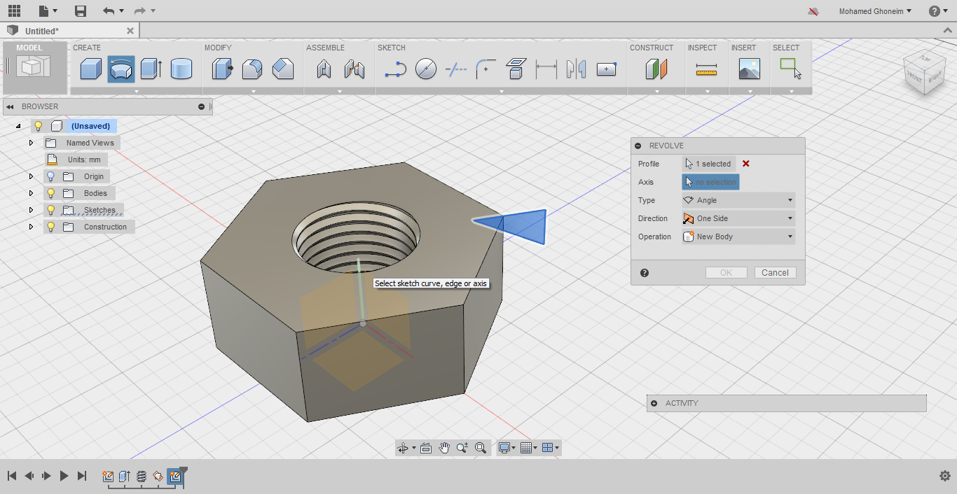
fig.33: Revolve
- Select the sketched profile to revolve it.
fig.34: Revolve
- When you select Axis, the origin planes and axes are visible.
- Select the highlighted axis (the axis passing through the hole of the nut).
- For this reason, I have chosen previously to reference the origin of the polygon on the origin point. This is defining your sketch relations.
fig.35: Revolve
- Left click OK to confirm your selections.
fig.36: Visually review your model
- What if after you finished the model, there is something you think is wrong and needs correcting?, will you start over? will you undo until you reach the step where the mistake happened?
- I hope you didn't do any of these.
- The following example shall give you an idea how mistakes can be fixed.
fig.37: Modifying a finished model
- Expand the sketches label from the design tree.
fig.38: Modifying a finished model
- Light the Sketch2 label lamp.
fig.39: Modifying a finished model
- Right click Sketch2's label and choose Edit Sketch.
fig.40: Modifying a finished model
- You can drag the highlighted point and manipulate its location
fig.41: Modifying a finished model
fig.42: Modifying a finished model
- You can change the view by the view cube (or maybe hide the Body) to easily reach this other point.
fig.43: Modifying a finished model
- Drag the point around to modify the parameters of the triangular profile.
fig.44: Modifying a finished model
- Stop Sketch to be able to view the effect of the recently-made changes.
fig.45: Modifying a finished model
- Well, not exactly what I was looking for. Should I repeat editing the sketch and finishing it to view the effect? no?
fig.46: Modifying a finished model
- While the sketch is still visible, try and drag on of the acute-angle points.
fig.47: Modifying a finished model
- Changes are instant.
fig.48: Modifying a finished model
- After you are done modifying the sketch and its consequent feature, you can hide the sketch by turning that lamp off. (Just left click it)
fig.49: A hexagonal nut
- All done!
Brief Summary:
You can save (steps, time, effort) by deciding a smart/well-referenced profile upon which the body will be built. Like for example, sketching a polygon and a circle in its center instead of extruding a polygon, then creating a hole in it.
Being able to construct planes, axes and points allows you to create sketch profiles freely anywhere and accordingly add features (extruded features, revolved features, etc).
Because the relations on which the geometrical features are built are well-defined, you can modify these relations and make real-time modifications.
Thank you for your time and attention. I hope it was useful.


No comments:
Post a Comment